
Traffic Safety Manual
Traffic Safety consists of maintaining and improving traffic safety, this includes, but is not limited to, street signs, speed limits, roadside barriers, and parking along the roads and streets under the jurisdiction of Boone County.
Table of Contents
Section 1: Introduction
The Traffic Safety Manual provides guidelines and procedures that will be used as goals to maintain and improve traffic safety along the roads and streets under the jurisdiction of Boone County. Maintaining and improving traffic safety is a very complex problem. Although this manual will be used by county personnel and officials to determine courses of action in many cases, it is not all inclusive and is not intended to be used as a substitute for engineering judgment or to replace applicable design standards.
This manual utilizes information from the following sources:
- U.S. Department of Transportation, Federal Highway Administration. Manual on Uniform Traffic Control, Millennium Edition . December 2000.
- American Association of State Highway and Transportation Officials. A Policy on Geometric Design of Highways and Streets . 1994.
- American Association of State Highway and Transportation Officials. Guidelines for Geometric Design of Very Low-Volume Local Roads (ADT<=400) . 2001.
- American Association of State Highway and Transportation Officials. Roadside Design Guide . 1996.
Section 2: Traffic Signing at Intersections
Traffic control devices are necessary for regulating, warning, and guiding traffic, and are a primary determinant in the safe and efficient operation of intersections. The Manual on Uniform Traffic Control (MUTCD) outlines national standards for when and where traffic control is warranted. American Association of State Highway and Transportation Officials (AASHTO) sets forth guidelines for variables that impact traffic control such as sight distance requirements.
The uses of regulatory signs inform highway users of traffic laws or regulations and indicate the applicability of legal requirements that would not otherwise be apparent. Common regulatory signs include the STOP sign (R1-1) and YIELD sign (R1-2). The use of the Street Name sign informs the highway user of the street location and enables the highway user and the safety personnel to navigation to homes, businesses, etc. The application of stop signs, multi-way stop signs, yield signs, and street name signs are discussed in the following sections.
2.1 Stop Signs
STOP signs are intended for use where traffic is required to stop. The standard size of a STOP sign used in Boone County will be 30-inch x 30-inch and the bottom of the sign will not be less than 5 feet from the ground. Where greater emphasis or visibility is required, a larger size sign should be considered.
Table 1 summarizes the condition that may require the use of the STOP sign. The STOP sign should be used only where warranted because it can cause a substantial inconvenience to motorists. Prior to the application of a STOP sign, consideration of less restrictive measures, such as the YIELD sign should be examined. Periodic reviews of existing installations may be conducted to determine if less restrictive control or no control could accommodate traffic demands safely and more effectively.
In a situation where two main highways intersect, the STOP sign or signs should normally be posted on the minor street to stop the lesser flow of traffic. Traffic engineering studies, however, may justify the installation of a STOP sign or signs on the major street. Such a situation may occur at a three-way intersection where safety considerations may justify stopping the greater flow of traffic to permit a left-turning movement.
STOP Signs will be replaced by the County within 24 hours of notification that a STOP Sign has been stolen or damaged.
Back to Top2.2 Multi-way Stop Signs
A multi-way stop installation is useful as a safety measure at some locations. Table 1 includes conditions that may warrant the installation of a multi-way stop.
At a multi-way stop intersection, Boone County will use a supplementary plate (R1-3) 12-inch x 6-inch in size that will be mounted just below the STOP sign. If the number of approach legs to the intersection is three or more, the numeral on the supplementary plate shall correspond to the actual number of legs (i.e., 3-WAY or 4-WAY). If all streets of the intersection are controlled by STOP signs, the supplementary plate may state ALL-WAY, instead of the number of approach legs.
Table 1. Summary of Guidance and Options for Stop and Multi-way Stop Conditions
| Traffic Control Devices | Conditions That Might Warrant a STOP Sign |
|---|---|
|
STOP Sign R1-1  Standard Size is 30" x 30" |
1. Intersection of a less important road with a main road where application of the normal right-of-way rule would not be expected to provide reasonably safe operation. |
| 2. Street entering a through highway or street. | |
| 3. Unsignalized intersection in a signalized area. | |
| 4. High speeds, restricted view, or crash records indicate a need for control by the STOP sign. | |
|
MULTI-WAY STOP Signs (Use in conjunction with R1-1) R1-3  Standard Size is 12" x 6" R1-4  Standard Size is 18" x 6" |
1. Where traffic signals are justified, the multi-way stop is an interim measure that can be installed quickly to control traffic while arrangements are being made for the installation of the traffic control signal. |
| 2. A crash problem, as indicated by 5 or more reported crashes in a 12-month period that are susceptible to correction by a multi-way stop installation. Such crashes include right- and left-turn collisions as well as right-angle collisions. | |
3. Minimum volumes:
|
|
| 4. Where no single criterion is satisfied, but where criteria 2, 3a, and 3b are all satisfied to 80 percent of the minimum values. Criterion 3c is excluded from this condition. | |
5. Other criteria that may be considered in an engineering study include:
|
|
| For ADT <= 400 | 1. For low-volume roads where engineering judgment or study indicates that either of the following conditions applies:
|
Source: Manual on Uniform Traffic Control Devices, Millennium Edition. (Section 2B.05 through 2B-07, & 5B.03)
Back to Top2.3 Yield Signs
The YIELD sign assigns right-of-way to traffic on certain approaches to an intersection. Vehicles controlled by a YIELD sign need stop only when necessary to avoid interference with other traffic that is given the right-of-way. Table 2 outlines conditions when a YIELD sign may be warranted.
The standard size of a YIELD sign used in Boone County will be 36-inch x 36-inch x 36-inch and the bottom of the sign not be less than 5 feet from the ground. YIELD signs generally should not be placed to control the major flow of traffic at an intersection. However, YIELD signs may be installed to control traffic movement where a majority of drivers in that movement are making right turns. At such an intersection, YIELD signs should not be erected on more than one approach. Table 2 summarized the guidance and options conditions for YIELD sign usage as outlined in the MUTCD.
Table 2. Summary of Guidance and Options for Yield Conditions
| Traffic Control Devices | Conditions That Might Warrant a YEILD Sign |
|---|---|
|
YEILD Sign R1-2  Standard Size is 36" x 36" x 36" |
1. At the entrance to an intersection where it is necessary to assign right-of-way and where the safe approach speed on the entrance exceeds 10 miles per hour. |
| 2. If controlling a merge-type movement on the entering roadway where acceleration geometry and/or sight distance is not adequate for merging traffic operations. | |
| 3. At the second crossroad of a divided highway, where the median width is 30 feet wide or greater. A STOP sign may be installed at the entrance to the first roadway of the divided highway, and a YIELD sign may be placed at the entrance to the second roadway. | |
| 4. At an intersection where a special problem exists and where engineering judgment indicates the problem to be susceptible to correction by use of the YIELD sign. | |
| For ADT <= 400 | 1. For low-volume roads where engineering judgment or study indicates that either of the following conditions applies:
|
Source: Manual on Uniform Traffic Control Devices, Millennium Edition. (Section 2B.08 through 2B-09, & 5B.03)
Back to Top2.4 Location of Stop & Yield Signs
A STOP sign should be erected at the point where the vehicle is to stop or as near thereto as possible. If accident trends or engineering analysis indicate a reoccurring violation of this standard, the County should consider adding a stop line and/or the word STOP on the pavement. A YIELD sign should be erected in the same manner, at the point where the vehicle is to stop if necessary to yield the right-of-way. Where a marked crosswalk on pavement exists, the sign should be erected approximately 4 feet in advance of the crosswalk line nearest to approaching traffic. Stop signs and yield signs will be located on county maintained roads and/or private roads where they intersect county maintained roads when warranted.
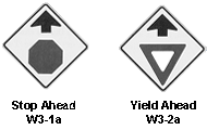
In a situation where the visibility of a STOP sign or a YIELD sign is restricted, the STOP sign or YIELD sign shall be located as specified, and a STOP AHEAD (W3-1a) or a YIELD AHEAD (W3-2a) sign shall be erected in advance of the STOP or YIELD sign. The minimum standard size for the STOP AHEAD and YIELD AHEAD warning signs to be used will be 30-inch x 30-inch. In instances where there is a history of poor observance of the STOP sign, the County will install a STOP AHEAD warning sign. The placement of the STOP AHEAD and YIELD AHEAD sign shall be determined from Table 6. Figure 1 displays the advance warning signs to be used by Boone County .
Figure 1. Stop Ahead and Yield Ahead Warning Signs
2.5 Intersections with No traffic Control
In a situation where an intersection crossing is not controlled by yield signs, stops signs, or traffic signals, the operator of a vehicle approaching an intersection must be able to perceive a hazard in sufficient time to alter the vehicle's speed as necessary before reaching the intersection. Figure 2 displays an intersection with no traffic control. In this situation, no obstructions should be present within the sight triangle. To determine the appropriate distance (d) of the sight triangle legs, the speeds along the major and minor roads should be determined. Based upon these speeds, Table 3 will be used to determine the dimensions of the sight triangle legs.
Figure 2. Example of Intersection with No Traffic Control
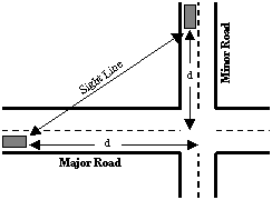
Table 3. Sight Distance required at No Control Intersections
| Speed | ADT > 400 Distance "d" of the Sight Triangle Leg 1,3 |
ADT <= 400 Distance "d" of the Sight Triangle Leg 2,3 |
|---|---|---|
| 15 mph | 70 ft | 60 ft |
| 20 mph | 90 ft | 80 ft |
| 25 mph | 115 ft | 95 ft |
| 30 mph | 130 ft | 120 ft |
| 35 mph | 145 ft | 140 ft |
| 40 mph | 180 ft | 170 ft |
| 45 mph | 200 ft | 210 ft |
| 50 mph | 220 ft | 255 ft |
| 55 mph | 250 ft | 300 ft |
| 60 mph | 280 ft | 350 ft |
Notes
Source: A Policy on Geometric Design of Highways and Streets, AASHTO, 1994. (Table IX-7, page 699)
Source: Guidelines for Geometric Design of Very Low-Volume Roads, 2001 (Exhibit 14, p.45)
Additional consideration should be given to intersection approaches that exceed 3 percent grade.
For example, a roadway at 40 miles per hour intersecting a roadway at 25 miles per hour and an average daily traffic (ADT) of greater than 400 vehicles per day would result in the legs of the sight triangle equal to 180 feet and 115 feet respectively. These, or greater distances, will permit a vehicle on either road to change speed before reaching the intersection.
Non-controlled intersections should be used only in the design of intersections on two lane roads where sight distances are adequate. Intersections with sight triangles having adequate sight distance may still require control based on engineering judgment. Where this minimum sight triangle cannot be provided, traffic control devices should be used to slow down or stop vehicles on one or both roads even if both roads are lightly traveled. Existing conditions will be addressed as they become evident and as funding allows.
Back to Top2.6 Intersection Stopping Sight Distance
Sight distance is the length of roadway ahead visible to the driver. The minimum stopping sight distance available on a roadway is the distance to enable a vehicle traveling at or near the design speed to stop before reaching a stationary object in its path. Table 4 outlines the stopping sight distance guidelines.
Table 4. Stopping Sight Distance Requirements
| Speed | ADT > 400 Minimum Stopping Sight Distance 1 |
ADT <= 400 Minimum Stopping Sight Distance 2 |
|---|---|---|
| 20 mph | 100 ft | 95 ft |
| 25 mph | 150 ft | 125 ft |
| 30 mph | 190 ft | 165 ft |
| 40 mph | 250 ft | 250 ft |
| 45 mph | 310 ft | 300 ft |
| 50 mph | 370 ft | 350 ft |
| 55 mph | 430 ft | 405 ft |
| 60 mph | 515 ft | 470 ft |
Sources
A Policy on Geometric Design of Highways and Streets, AASHTO, 1994. (page 120)
Guidelines for Geometric Design of Very Low Volume Local Roads, 2001 (Exhibit 8, p.34)
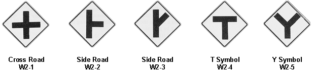
Where adequate stopping sight distance at the intersection is not available to the through traffic at the posted speed, then intersection warning signs (W2-1 through W2-5) should be installed on the uncontrolled road approaches. The standard size of the intersection warning signs used in Boone County will be 30-inch x 30-inch. Examples of these signs are displayed in Figure 3. The placement of these signs is determined by using Table 6.
Figure 3. Intersection Warning Signs
Source: Manual on Uniform Traffic Control Devices, Millennium Edition. (section 2C.34).
2.7 Unwarranted Traffic Control Devices
Stop signs will not be installed by the County solely to control vehicle speeds or divert traffic. STOP signs installed in the wrong places for the wrong purposes can create more problems than are solve. Studies have shown that there is a high incidence of intentional violations where stop signs are installed to control speed. These studies showed that vehicle speed was reduced in the immediate vicinity of the stop signs, but vehicle speeds were actually higher between intersections than they would have been if these signs had not been installed. At the right place and under the right conditions, a STOP sign tells the drivers and pedestrians who has the right of way.
Back to Top2.8 Street Name Signs
Street Name signs are used to identify roads and are installed at street intersections regardless of other route signs. For roads with a speed limit less than 60 miles per hour, the Street Name sign lettering height shall be at least 6 inches for upper case-letters and 4.5 inches for lower-case letters. For local roads with a speed limit of 60 miles per hour or greater, the Street Name sign lettering height shall be at least 9 inches for upper case-letters and 6 inches for lower-case letters. At intersections with two different speed limits, the higher speed limit will prevail when determining Street Name sign letter height.
Any supplementary lettering to indicate the type of street, such as Street, Avenue, or Road, shall have a minimum height of 3 inches and conventional abbreviations may be used. Coordinates shall be used for all County maintained roads, except for internal subdivision roads or roads of shared jurisdiction with municipalities. The coordinates shall be located on the top, right hand corner of the Street Name sign and shall be a minimum of 2 inches in height.
The Street Name sign shall be retroreflective or illuminated to show the same shape and similar color both day and night. Street Name signs for all county maintained roads shall have a white legend on a green background. Street Name signs for all privately maintained roads shall have a black legend on a white background. An informational placard stating it is a private road will be placed below the Street Name sign.
At intersections of crossroads where the same road has two different street names for each direction of travel, both street names may be shown on the same signpost. Directional arrows shall be used to designate the street name to the location of the street.
Divided highways that intersect with County maintained roads may have Street Name signs placed on each side of the intersections unless placement of a sign in the median is permitted. On principal arterials, Street Name signs should be placed at least on diagonally opposite corners so that they will be on the far right side of the intersection for traffic on the major street. In subdivisions and rural intersections, at least one Street Name sign should be located at each intersection. The Street Name sign for each road of the intersection shall be mounted on the same post and the Street Name sign faces shall be parallel to the street they name. The Street Name signs shall be at installed least 5 feet off the ground measured from the bottom of the sign to the near edge of the pavement. Street Name signs may be mounted on the same post as Stop or Yield signs.
The County shall post and maintain Street Name signs on all county maintained roads and at the entrances of privately maintained roads. The Street Name signs shall only contain street names adopted by the Commission. The Street Name sign posting of the privately maintained roads will be located at the intersection of the county maintained road and the privately maintained road within the county right-of-way, whenever possible. If the privately maintained road intersects with a State right of way, the Street Name sign will be placed in the State right of way as permitted. The County will not provide and maintain Street Name signs for the internal roads of a privately maintained subdivision.
Back to TopSection 3: Road Speeds
3.1 Design Speeds
The design speed for local, collector, and arterial roads is located in the Boone County, Missouri, Roadway Regulations, Chapter II, Road, Bridge & Right of Way Regulations. The design speed is based upon the road type. The County may complete an engineering study for different speed limits where conditions of safety dictate and costs can be supported. In spot locations or segments where design speeds cannot be economically provided, appropriate warning and traffic control signs or devices will be installed.
Back to Top3.2 Posting of Speed Limits
Speed limits on County roads will be posted adjacent to intersecting State routes or other major County roads and at other strategic locations where it becomes apparent that drivers should be reminded of the appropriate route speed. A speed limit will be posted by default or by performing an engineering study. If it is determined that a study is to be performed, the following factors will be considered when establishing the speed limit (MUTCD, page 2B.11):
- Road surface characteristics, shoulder condition, grade, alignment and sight distance;
- The 85 th -percentile speed and pace speed;
- Roadside development and culture and roadside friction;
- Parking practices and pedestrian activity; and
- Reported accident experience for a recent 12-month period.
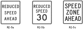
The Reduced Speed Ahead (R2-5) should be used in rural areas to inform motorists of a reduced speed zone when an advance notice is needed to comply with the speed limit posted ahead. A Speed Limit sign erected at the beginning of the zone where the altered speed limit applies shall always follow this sign. The minimum standard size of Reduced Speed Ahead signs will be 24-inch x 30-inch. Figure 4 displays examples of the Reduced Speed Ahead signs.
Figure 4. Reduced Speed Ahead Signs (R2-5 series)
3.3 Advisory Speed Limits on Turns and Curves
Whenever it is practical, the curves along a road in Boone County will be constructed at the overall road design speed. However, when this cannot be done on new roads or has not been done on existing roads, studies will be completed to determine if warning signs are needed. Whether or not a curve should be provided with warning signs depends on the posted speed limit and the computed or measured safe travel speed. If the radius and super elevation is known, the safe travel speed can be calculated. On County roads where this information is not available, measurement of the safe speeds will be completed using an instrument called a ball bank indicator1 mounted on a survey vehicle. A series of test runs will be conducted on each curve along a route to determine the ball deflection readings for various speeds. Readings of 10 degrees will be used to identify the safe speed of the curve.
If the safe curve speed is less than the posted speed limit, then either turn or curve warning signs (i.e., W1-1, W1-2, W1-3, W1-4, or W1-5) will be installed as prescribed in the MUTCD, section 2C.06. Examples of the turn and curve signs are shown in Figure 5. Turn signs should be used for speeds of 30 miles per hour or less, and curve signs should be used for speeds of greater than 30 miles per hour. Additional protection may be provided by use of advisory speed plates. The minimum standard size for signs W1-1 through W1-5 will be 30-inch x 30-inch.
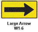
Winding road signs are applicable where three or more turns or curves, are separated by less than 600 feet of tangent. For added emphasis on turns, a large arrow sign (W1-6) may be placed on the outside of a turn. The minimum standard size for the large arrow sign will be 48-inch x 24-inch. The large arrow sign is shown in Figure 6.
Table 5 sets forth guidelines to determine the appropriate warning signs based on the results of the ball bank indicator. The appropriate placement of the turn or curve warning signs shall be determined based upon Table 6.
1 The ball bank indicator consists of a steel ball sealed in a curved glass tube with a liquid. The ball is free to move except for the dampening effect of the liquid. The movement or deflection of the ball up either side of the curved glass tube is governed by the roadway superelevation (i.e. gravity) and the centrifugal force developed as the survey vehicle travels around a curve at a given speed.
Figure 5. Curve and Turn Signs
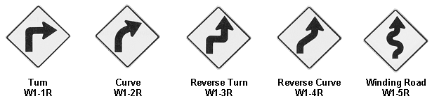
Source: Manual on Uniform Traffic Control Devices, Millennium Edition (page 2C-9).
Figure 6. Large Arrow Sign
Source: Manual on Uniform Traffic Control Devices, Millennium Edition (page 2C-9).
Table 5. Signing for Curves and Turns
| Usual Operating Speed | Advisory Speed Based on Ball Bank Indicator | ||||||||
|---|---|---|---|---|---|---|---|---|---|
| 60 mph | 55 mph | 50 mph | 45 mph | 40 mph | 35 mph | 30 mph | 25 mph | 20 mph or less | |
| 60 mph | - | C | C | CA | CA | CA | TA | TA | TA |
| 55 mph | - | - | C | C | CA | CA | TA | TA | TA |
| 50 mph | - | - | - | C | C | CA | TA | TA | TA |
| 45 mph | - | - | - | - | C | C | TA | TA | TA |
| 40 mph | - | - | - | - | - | C | T | TA | TA |
| 35 mph | - | - | - | - | - | - | T | T | TA |
| 30 mph | - | - | - | - | - | - | - | T | T |
| 25 mph | - | - | - | - | - | - | - | - | T |
| 20 mph or less | - | - | - | - | - | - | - | - | - |
C = Curve Sign, Reverse Curve Sign (or winding road sign if applicable)
T = Turn Sign, Reverse Turn Sign (or winding road sign if applicable)
A = Advisory Speed Plate
Source: Handbook of Traffic Control Practices for Low Volume Rural Roads, Kansas Department of Transportation, 1991
(modified to reflect practice of Missouri Department of Transportation)
Table 6. A Guide for Advance Warning Sign Placement Distance
| Posted or 85th Percentile Speed | Advance Placement Distance Table 6, Supplemental Note 1 | ||||||
|---|---|---|---|---|---|---|---|
| Condition A: High Judgment Required Table 6, Supplemental Note 2 | Condition B: Stop Condition Table 6, Supplemental Note 3 | Condition C: Deceleration to the Listed Advisory Speed for the Condition Table 6, Supplemental Note 4 | |||||
| 10 mph | 20 mph | 30 mph | 40 mph | 50 mph | |||
| 20 mph | 175 ft | N/ATable 6, Supplemental Note 5 | N/ATable 6, Supplemental Note 5 | - | - | - | - |
| 25 mph | 250 ft | N/ATable 6, Supplemental Note 5 | 100 ft | N/ATable 6, Supplemental Note 5 | - | - | - |
| 30 mph | 325 ft | 100 ft | 150 ft | 100 ft | - | - | - |
| 35 mph | 400 ft | 150 ft | 200 ft | 175 ft | N/ATable 6, Supplemental Note 5 | - | - |
| 40 mph | 475 ft | 225 ft | 275 ft | 250 ft | 175 ft | - | - |
| 45 mph | 550 ft | 300 ft | 350 ft | 300 ft | 250 ft | N/ATable 6, Supplemental Note 5 | - |
| 50 mph | 625 ft | 375 ft | 425 ft | 400 ft | 325 ft | 225 ft | - |
| 55 mph | 700 ft | 450 ft | 500 ft | 475 ft | 400 ft | 300 ft | N/ATable 6, Supplemental Note 5 |
| 60 mph | 775 ft | 550 ft | 575 ft | 550 ft | 500 ft | 400 ft | 300 ft |
| 65 mph | 850 ft | 650 ft | 650 ft | 625 ft | 575 ft | 500 ft | 375 ft |
Notes
- The distances are adjusted for a sign legibility distance of 175 feet which is the appropriate legibility distance for the 5 inch Series D word legend. The distances may be adjusted by deducting another 100 feet if symbol signs are used. Adjustments may be made for grades if appropriate.
- Typical conditions are locations where the road user must use extra time to adjust speed and change lanes in heavy traffic because of a complex driving situation. Typical signs are Merge, Right Lane Ends, etc. The distances are determined by providing the driver with PIEV time of 6.7 to 10.0 seconds plus 4.5 seconds for vehicle maneuvers minus the legibility distance of 175 feet for the appropriate sign.
- Typical condition is the warning of a potential stop situation. Typical signs are Stop Ahead, Yield Ahead, or Signal Ahead. The distances are based on the 1990 AASHTO Policy for stopping sight distance providing a PIEV time of 2.5 seconds, friction factor of 0.30 to 0.40, minus the sign legibility distance of 175 feet.
- Typical conditions are locations where the road user must decrease speed to maneuver through the warned condition. Typical signs are Turn, Curve, or Cross Road . The distance is determined by providing a 1.6 seconds PIEV time, a vehicle deceleration rate of 10 feet per second 2 , minus the sign legibility distance of 175 feet.
- No suggested minimum distances are provided for these speeds, as placement location is dependent on site conditions and other signing to provide an adequate advance warning for the driver.
Source: Manual on Uniform Traffic Control Devices, Millennium Edition (Table 2C-4, page 2c-7)
Back to Top3.4 Posting of Lower Speed Limits
The County does not endorse the posting of lower speed limits solely based on local requests to "improve safety." A common belief is that posting a speed limit will influence drivers to drive at that speed. The facts indicate otherwise.
Many studies conducted over several decades in all parts of the country have shown that a driver's speed is influenced more by the appearance of the roadway and the prevailing traffic conditions than it is by the posted speed limit. Some drivers will obey the lower posted speed while others will feel it is unreasonable and simply ignore it. This disrupts the uniform traffic flow and increases accident potential between the faster and the slower divers. When traffic is traveling at different speeds, the number of gaps in traffic to permit safe crossing is reduced. Pedestrians also have greater difficulty in judging the speed of approaching vehicles.
Back to Top3.5 Changing of Posted Speed Limits
A posted speed limit shall be changed only by Commission Order.
Back to TopSection 4: Pavement Markings
The decisions regarding which routes should be provided with pavement markings will be based on detailed engineering analyses of traffic accidents, traffic volumes, roadway widths, and expected striping life. Markings shall be yellow, white, red, or blue. The colors for markings shall conform to the standard highway colors. Black in conjunction with one of the above colors shall be a usable color for object markers. All pavement markings will be installed in conformance with MUTCD.
This section discusses center lines, passing zones, pavement edge lines, stop lines, crosswalk lines, and temporary pavement markings. The MUTCD guidance will be used for any other marking situations, such as left turn lanes, when encountered.
4.1 Center Lines
Center line marking shall be used to delineate the separation of traffic lanes that have opposite direction of travel on a road and shall be yellow. Center line markings are placed on paved roads under the following conditions (MUTCD, Section 3B.01):
- Center line markings shall be placed on all paved urban arterials and collectors that have a travel width of 20 feet or more and an Average Daily Traffic (ADT) of 4,000 vehicles per day or greater;
- Center line markings shall be placed on all paved rural arterials and collectors that have a traveled width of 18 feet or more and an ADT of 3,000 vehicles per day or greater;
- Center line markings may be placed on paved two-way traveled roads that are 16 feet or more in width and an ADT of 400 vehicles per day or greater. Engineering judgment should be used in determining whether to place center line markings because of the potential for traffic encroaching on the pavement edges, traffic being affected by parked vehicles, and traffic encroaching into the opposite traffic lane; and
- At other locations where an engineering study indicates a need for center line markings.
The County may use center line markings on paved road wider than 16 feet with priority given to the following conditions:
- Speed limits;
- Horizontal and vertical curves;
- Average daily traffic volume; and
- Road classification.
The pavement width used in this analysis will be the predominant width, which exists along a segment of at least three miles in length. The County will not provide center line markings for subdivisions roads.
The center line markings on two-lane, two-way roads shall be one of the following (MUTCD, Section 3B.01):
- Two-direction passing zone marking of a normal broken yellow line where crossing the center line markings for passing with care is permitted for traffic traveling in either direction;
- One-direction no-passing zone markings consisting of a normal broken yellow line and a normal solid yellow line where crossing the center line marking for passing with care is permitted for the traffic traveling adjacent to the broken line, but is prohibited for traffic traveling adjacent to the solid line; or
- Two-direction no-passing zone markings consisting of two normal solid yellow lines where crossing the center line markings for passing is prohibited for traffic traveling in either direction.
The center line markings on undivided two-way roads with four or more traffic lanes shall be the two-direction no-passing zone markings consisting of two normal solid yellow lines. The lanes of the same direction of the same direction will be divided by normal broken white lines.
The width and pattern of the center line markings shall conform to the following standards (MUTCD, Section 3A.06):
- A normal solid yellow line shall be 4 to 6 inches wide; and
- A normal broken yellow line shall be 10 feet long line segments 4 to 6 inches wide with 30-foot gaps.
4.2 Passing Zones
Where center lines are installed, no-passing zones shall be established at vertical curves, horizontal curves, and other locations where an engineering study indicates passing must be prohibited.
A no-passing zone on a horizontal curve or a vertical curve is warranted where the sight distance is less than the minimum passing sight distance as listed in Table 7. The passing sight distance on a horizontal curve is the distance measured along the center line between two points 3.5 feet above the pavement on a line tangent to the embankment or other obstruction that restricts the view on the inside of the curve. The passing sight distance on a vertical curve is the distance at which an object 3.5 feet above the pavement surface can just be seen from a point 3.5 feet above the pavement. The speed is the prevailing off-peak 85 th -percentile speed or the posted speed limit, whichever is higher. The no-passing zone should be marked where the sight distance is equal to or less the minimum passing sight distance.
Table 7. Minimum Passing Sight Distance
| Speed | Minimum Passing Sight Distance |
|---|---|
| 25 mph | 450 ft |
| 30 mph | 500 ft |
| 35 mph | 550 ft |
| 40 mph | 600 ft |
| 45 mph | 700 ft |
| 50 mph | 800 ft |
| 55 mph | 900 ft |
| 60 mph | 1,000 ft |
Source: Manual on Uniform Traffic Control Devices, Millennium Edition (Page 3B-9)
Back to Top4.3 Pavement Edge Lines
Pavement edge line markings delineate the left or right edge of the road. Edge line markings may be placed on roadway features such as horizontal curves, narrow bridges, pavement width transitions, and curvilinear alignments. They have unique value as a visual reference for the guidance of drivers during adverse weather and visibility conditions. Pavement edge lines on two-lane roadways shall be a solid white color and edge lines shall not be continued through intersections or be broken for driveway access.
Edge line markings may be placed on paved roads with following characteristics (MUTCD, Section 3B.07):
- Rural arterials and collectors with a traveled way of 20 feet or more in width and an ADT of 3,000 vehicles per day or greater;
- At other paved streets and highways where an engineering study indicates a need for edge line markings; or
- Where edge delineation is desirable to minimize unnecessary driving on paved shoulders or on refuse areas that have lesser structural pavement strength than the adjacent roadway.
Edge line marking should not be placed where an engineering study indicates that providing them would decrease safety.
Back to Top4.4 Stop Lines
Stop lines are used in both rural and urban areas where it is important to emphasis the point behind which vehicles are required to stop in compliance with a STOP sign, traffic signal, or other legal requirement. Stop lines are solid white lines, normally 12 to 24 inches wide, extending across all approach lanes.
Stop lines are placed at the desired stopping point and should be placed to allow sufficient sight distance for all approaches to an intersection. The stop line should not be placed more than 30 feet or less than 4 feet from the nearest edge of the intersecting roadway. If a stop line is used in conjunction with a STOP sign, it should be placed in line with the STOP sign. However, if the sign cannot be located exactly where vehicles are expected to stop, the stop line should be placed at the stopping point. Stop lines used in conjunction with a crosswalk are placed 4 feet in advance of and parallel to the nearest crosswalk line.
Back to Top4.5 Crosswalk Lines
Crosswalk markings provide guidance for pedestrians crossing roads by defining and delineating paths. Crosswalks are marked at intersections where there is substantial conflict between vehicle and pedestrian movements. Marked crosswalks should also be provided at other appropriate points of pedestrian concentration. At the non-intersection locations, crosswalk markings legally establish the crosswalk and are used to alert road users of pedestrian crossing point across roads not controlled by traffic stops. An engineering study should be required before they are installed at locations away from intersections.
Crosswalk lines shall be solid white lines used to mark both edges of the crosswalk. The minimum width of the crosswalk line shall be 6 inches and the crosswalk lines shall not be spaced less than 6 feet apart. Under special circumstances where a stop line is not provided, where vehicular speeds exceed 35 miles per hour, or where crosswalks are unexpected, it may be desirable to increase the width of the crosswalk line up to 24 inches in width. Crosswalk lines on both sides of the crosswalk should extend across the full width of the pavement to discourage diagonal walking between crosswalks.
Since non-intersectional pedestrian crossings are generally unexpected by the motorist, warning signs should be installed and adequate visibility provided by parking prohibitions.
Back to Top4.6 Temporary Pavement Markings
When newly paved roads that warrant pavement markings are open to traffic prior to receiving permanent pavement marking, temporary pavement markings shall be used to delineate the separation of two-way traffic. The temporary pavement markings shall consist of raised pavement markers with a height of at least 0.4 inches mounted on the road surface. The temporary pavement markings shall be reflective and the color shall conform to the color of the marking for which they substitute. The distance between each temporary pavement marking shall be 25 feet.
Back to TopSection 5: Roadside Barriers
The County may use guardrails to shield motorists from natural or man-made obstacles located near the road. The primary purpose of the guardrail is to prevent the vehicle, if it inadvertently leaves the road, to strike a fixed object or travel a terrain feature that is considered more dangerous than hitting the guardrail barrier. A guardrail is warranted if it reduces the severity of the potential accident. In other words, if the consequences of a vehicle striking a fixed object or running off the road are believed to be more serious than hitting a traffic barrier, than a guardrail is considered warranted. Guardrails are used typically to provide protection from steep embankment heights, fixed objects, and pedestrians and bicyclists. Table 8 outlines the guardrail warrants for non-traversable terrain and roadside obstacles.
Table 8. Warrant Considerations for Guardrail Placement
| Terrain or Obstacle Table 8, Supplemental Note 1, Table 8, Supplemental Note 2 | Warrant |
|---|---|
| Bridge Piers, Abutments, and Railing Ends | Shielding generally required. |
| Boulders | A judgment decision based on nature of fixed object and likelihood of impact. |
| Culverts, Pipes, Headwalls | A judgment decision based on size, shape, and location of obstacle. |
| Cut Slopes (smooth) | Shielding not generally required. |
| Cut Slopes (rough) | A judgment decision based on likelihood of impact. |
| Ditches (transverse) | Shielding generally required if likelihood of head-on impact is high. |
| Embankments | A judgment decision based on fill height and slope. |
| Retaining Walls | A judgment decision based on relative smoothness of wall and anticipated maximum angle of impact. |
| Signs/Luminaire Supports Table 8, Supplemental Note 3 | Shielding generally required for non-breakaway supports. |
| Trees | A judgment decision based on site-specific circumstances. |
| Utility Poles | Shielding may be warranted on a case-by case basis. |
| Permanent Water Bodies | A judgment decision based on location and depth of water and likelihood of encroachment. |
Notes
- Shielding non-traversable terrain or a roadside obstacle is usually warranted only when it is within the clear zone and cannot practically or economically be removed, relocated, or made breakaway, and it is determined that the barrier provides a safety improvement over the unshielded condition.
- Marginal situations, with respect to placement or omission of a barrier, will usually be decided by accident experience, with at the site or at a comparable site.
- Where feasible, all sign and luminaire supports should be a breakaway design regardless of their distance from the road if there is reasonable likelihood of their being hit by an errant motorist.
Source: Roadside Design Guide, 1996 (p.5-5)
Embankment height and side slope are basic factors considered in determining if a guardrail is warranted. Table 9 lists the embankment height/side slope situations that may warrant a guardrail. Encroachment occurring due to the placement of the guardrail and the costs associated with the guardrail will also be considered when using this table.
Table 9. Embankment/Side Slope Warrants for Guardrail
| Side Slope (H:V) | Embankment Fill Height |
|---|---|
| 1.5:1 | 3 ft or steeper |
| 2:1 | 6 ft or steeper |
| 2.5:1 | 9 ft or steeper |
| 3:1 | 16 ft or steeper |
Note
- Encroachment occurring due to the placement of the guardrail and the costs associated with the guardrail will also be considered when using this table.
Source: Roadside Design Guide, 1996 (Figure 5.1, p. 5-3)
If it is not immediately obvious whether the barrier or the unshielded condition presents the greater risk, an engineering evaluation may be used. The warrant will be established by using a benefit to cost analyses. The evolution will take into account design speed, traffic volume, and costs associated with the barrier or improvements. The evaluation will typically look at three options.
- Remove or reduce the area of concern so that it no longer requires shielding;
- Install an appropriate barrier; and
- Leave the area of concern unshielded.
The use of guardrails to shield or protect drivers from roadside obstructions is generally not cost-effective for roads with an average daily traffic (ADT) less than 400 vehicles per day. A guardrail itself is a roadside obstacle and a significant proportion of vehicles impacts with guardrails produce injuries. The low frequency of collisions with guardrails and the cost associated with maintaining guardrails makes it impractical for using guardrails on low volume roads. Engineering judgment should be used in determining locations where guardrail should be used due to the potential of a severe accident due to departure from the road.
Back to TopSection 6: Non-Standard Traffic Control Devices
Boone County will avoid the use of non-standard and unproven traffic control devices such as Children at Play signs or Speed Bumps. Engineering assistance may be provided for neighbors that are interested in various traffic calming options.
6.1 Children at Play Signs
The Missouri Department of Transportation does not recognize the use of the SLOW - CHILDREN AT PLAY or similar messages sign. Parental concern for the safety of children in the street near home and a misplaced but wide-spread public faith in traffic signs to provide protection often prompt the request for these types of signs.
No factual evidence has been presented to document the sign's success in reducing pedestrian accidents, vehicle operating speeds, or legal liability. Studies have shown that many types of signs attempting to warn of normal conditions in residential areas have failed to achieve the desired safety benefits. If signs encourage parents and children to believe they have an added degree of protection, which the signs do not and cannot provide, a great disservice results. Children should not be encouraged to play within the street travel ways. This sign has long been rejected since it is a direct and open suggestion that this behavior is acceptable. Therefore, the County will not promote or provide the SLOW-CHILDREN AT PLAY sign.
Back to Top6.2 Traffic Calming
Traffic Calming is the application of techniques at a specific location that result in a reduction in vehicular speeds, traffic volumes, traffic noise, and accidents. The techniques may include educational programs, neighborhood speed watch programs, improvements in traffic signing, increased enforcement, reduction of speed limits (see Section 3.4), or physical alterations to the roadway to change driving patterns. The support of the residents where traffic calming is being considered is critical to the success of any neighborhood traffic management program and they must therefore be an integral part of any process.
A traffic calming project shall be designed and sealed by an engineer register in the State of Missouri . The traffic calming project shall include a traffic study. The design shall be reviewed and approved by the County. For existing neighborhoods, the design and construction of the project shall be at the expense of the neighborhood. For new subdivisions, the design and construction of the project shall be at the expense of the developer. The objectives of traffic calming can frequently be met without physical changes to a roadway. The least intrusive solution is always the preferred one from a traffic engineering perspective. The County Highway Administrator will not endorse the use of speed bumps, unwarranted stop signs, or arbitrary lowering of speed limits. The traffic calming devices shall comply with Traffic Calming: State of Practice, developed by the Federal Highway Administration (August 1999). The following are most commonly applied devices.
- Speed Humps: Speed humps are raised sections of the roadway constructed to reduce vehicular speeds. Similar to a speed bump, the speed hump is wider and has a more sloping side taper. The physical impact on passing vehicles is less severe at slow speeds than at higher speeds.
- Traffic Circles: A traffic circle is a large circular area in the middle of an intersection constructed to control the right-of-way of vehicles. The circle is used to decrease vehicular speeds on a residential street and may decrease traffic volume as well. Traffic approaching the intersection must drive around the circle and yield to those cars that have already entered the circle.
- Chicanes: A chicane is created by staggered curb extensions that are placed on both sides of the street. These curb extensions alternate on the street and force motorists to substantially decrease their speed when driving around them. In addition, depending on the design, motorists may have to yield to oncoming traffic, when the curb extension is designed to allow only enough space for one car to pass at a time. The extensions, often landscaped with bushes and trees, decrease the driver's line of sight, and therefore, decrease the speed with which the motorist can drive with comfort.
- Realigned Intersections: A realigned intersection is created by changes in alignment at T-intersections with straight approaches into curving streets that meet at right angles. A former straight through movement on the top of the T intersections becomes a turning movement.
- Center Island Narrowing: Center Island Narrowing is created by constructing raised islands along the center line of a street. The island narrows the travel lane at that location decreasing the speed that the motorist may drive with comfort.
- Textured Pavement: A textured pavement is a roadway surface paved with brick, concreted pavers, stamped asphalt, or other surface material that produces constant small changes in vertical alignment.
- Raised Crosswalks: A raised crosswalk is a flat raised area covering the entire intersection with ramps on all approaches. The raised area is often constructed with bricks or other textured materials. The crosswalk is usually raised to the sidewalk level of slightly below the sidewalk level.
Section 7: Parking Restrictions
On residential streets at least one unobstructed moving lane with a minimum width of 11 feet must be ensured even when parking occurs on both sides. In general, parking will not be allowed on curves where hazardous situations may be created. Engineering judgment will be used to determine if a parking restriction is warranted. Parking restrictions will be approved by the County Commission prior to posting.
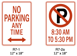
No parking shall be allowed on a road that has been signed or marked by means of official traffic control device. When it is determined that parking signs (R7 series) are needed, the proper installment of such signs shall follow the MUTCD, Sections 2B.34 to 2B.36. Parking signs should display the following information from top to bottom of the sign, in the order listed:
- Restriction or prohibition;
- Time of day if applicable, if not all hours; and
- Days of week if applicable, if not every day.
If the parking restriction applies to a limited area or zone, arrows or supplemental plaques should show the limits of the restriction.
Figure 7. Parking Restriction Signs
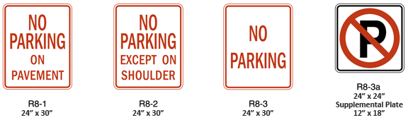
In rural districts, special parking prohibition signs may be used to emphasize that no person shall stop, park, or leave standing any vehicle on the paved or traveled part of the highway. The legend on rural parking signs must be appropriate to the restrictions imposed. Figure 8 displays common rural parking restriction signs.
Figure 8. Rural Parking Restriction Signs
Section 8: Traffic Signing at Low Water Crossings
Signing of low water crossings and other commonly flooded road areas is necessary to warn traffic of the potential for water to flow over the road surface. The County's goal is to install a series of three signs in advance of the potential flood areas in an effort to warn the motorist. The series of signs will consist of a 30-inch x 30-inch diamond-black on yellow warning sign stating “Flood Area Ahead”, a 30-inch x 30-inch diamond-black on yellow warning sign stating “Impassable During High Water”, and a 24-inch x 30-inch black on white regulatory sign stating “Do Not Enter When Flooded”. The signs will be encountered by the motorist in the order listed above. The series of sign will be used on all approaches to an identified flood area. Existing conditions will be address as they become evident and as funding allows.
The County will not use signs noting the depth of water over the road due to the potential for movement of the sign without the County's knowledge resulting in the sign depicting an inaccurate water depth.
Back to TopSection 9: Mowing, Tree Trimming, & Brush Cutting
The County will periodically mow shoulders along all non-subdivision County roads. All areas will be mowed to a width of approximately 5 feet from the edge of the road. Other sight distance sensitive areas will be mowed to a greater width, whenever possible, to improve sight distance. The County will attempt to achieve sight distances at intersection equal to or greater than the stopping sight distances recommended in Table 4. The County will complete tree trimming and brush cutting within the right of way by request or by staff recommendation. The County will work with the property owners in order to achieve proper sight distance.
The County will allow the adjacent property owners to mow their respective right-of-way areas.
Back to TopSection 10: Traffic Counts
Traffic count data is used to determine the frequency of vehicles on county maintained roads. Counts will be taken on roadway segments between intersections or other pertinent structure that may significantly affect the flow of traffic. The traffic count data will include, at a minimum, locations, volumes, times, and dates. Upon implementation of the GIS system, the traffic count information will be posted on a digital map of the County.
10.1 Procedure to Obtain a Traffic Count
There are four situations that may require the County to complete a traffic count on a certain road. Within each situation, a procedure is outlined to provide traffic count information and/or to complete a traffic count study. Traffic counts will not be taken during the winter months due to snow removal operations. These situations and procedures are as follows:
- Yearly Scheduled Counts: Traffic counts will be completed on all County maintained arterial and collector roads once every three years; the traffic counts will be completed on rural roads with a current average daily traffic (ADT) greater than 200 vehicles per day once every three years; and the traffic counts will be completed on the rural roads with an ADT less than 200 vehicles per day once every six years.
- Citizen Request: A citizen will be supplied with the of the most recent traffic count, the date of the traffic count, the location of the traffic count, and the anticipated year of the next count for the particular road requested. This information will be supplied, in writing, to the citizen. If the citizen feels that the traffic volume has significantly changed since the date of the latest traffic count, the citizen may request, in writing, for the County to complete a new traffic count of that particular road. The written request must include the reason the citizen believes the traffic volume has significantly increased since the most recent traffic count. The County will review the request and if deemed applicable will complete a new traffic count and supply the citizen, in writing, the information of the new traffic study. If the County does not agree with the citizen's request, the County will supply, in writing, the reason that the County does not deem the traffic study necessary.
- Engineering Safety Study: A traffic count may be required in conducting an engineering safety study of a road. The traffic count procedure will follow the requirements of the particular safety study.
- Joint Boone County/City of Columbia Study: A traffic count may be completed to assist the City of Columbia on a thoroughfare study. The traffic count will consist of a 24-hour count on hourly intervals to determine the ADT of County maintained roads near the city limits. This joint traffic count is completed once every three years.
10.2 Completion of a Traffic Count
In most situations, the traffic counts will be taken on a seven-day interval and from that information an ADT volume will be derived. The traffic count information will be recorded on an hourly basis unless the study requires the information to be recorded on the quarter hour basis. On certain occasions, a 24-hour or a 48-hour recording period with the data recorded on an hour or quarter hour basis may be used.
The tube type counters can be used to determine ADT and, if desired, speed or type of vehicle counted. The traffic count equipment will be placed near the intersections of roads or in the vicinity of structure anticipated to cause a wide variation in traffic counts. The equipment will be placed such that it can be secured to a permanent fixture near the roadway. Consideration should be given to anticipated movement of the vehicles and structures that may affect the traffic flow (i.e. business, subdivision). A summary of the weather for the week of monitoring should also be recorded. A map of the area should be sketched. The map should include, at the minimum, the follow items:
- Road names and numbers;
- Physical locations of the counters;
- GPS locations of the counters;
- North arrow; and
- Any other structures that may affect the flow of traffic.
The vehicle magnetic imaging (VMI) counters can be used for engineering studies that require more information than provided by the tube type counters. The VMI counters record the volume, speed, vehicle length classification, road surface temperature, road surface conditions (wet or dry), vehicle presence, and road occupancy. The VMI counters will only be used on paved roads and the road lanes need to be designated prior to placement of the VMI counters. As with the tube type counters, the VMI counters should be place near intersections or near structures that are anticipated to cause a variation in traffic flow. A map, as discussed above, should be used to record the field information.
Back to Top10.3 Data Output
Once the traffic count information has been obtained, the ADT should be recorded in yearly traffic count database and the information should be updated in the GIS system. All other information should be used and recorded as needed for the various traffic studies. A paper copy of the map, the data collector output, and any related correspondence should be placed in the Traffic Count File.
Back to TopSection 11: Traffic Safety Administration
Boone County shall establish and maintain certain data files tracking traffic accident history reports and traffic safety complaints. These data files provide the information necessary for the County to track and respond to traffic safety concerns in a timely matter and to document a discretionary decision, when required.
11.1 Accident Records
Traffic accident history reports available from the Missouri Highway Patrol Department will be reviewed semiannually. The pertinent information will then be summarized in table form and posted on the GIS system mapping, once implemented. The traffic accident information will include the following:
- The location;
- The type of accident;
- The time and date of the accident;
- The type of vehicle(s) involved;
- The injury status; and
- The damage to the vehicles.
This information will be review in evaluating safety projects in the County.
Back to Top11.2 Safety Concerns
Safety concerns as described by the general public, county employees or officials, law enforcement personnel, and others will be addressed by the County. When a safety concern has been expressed, the concern will be documented, in writing, and include the name, address, and telephone number of the individual expressing the concern, the location of the safety concern, and the type of safety problem.
Once the concern has been documented, the County will review the safety problem. The review may include a site visit to the location, the traffic count data, the accident history, and other documented complaints. From this information, the County will develop an evaluation of the site and a prioritization of the safety concern as compared with other safety projects around the County. If applicable, an engineering design to improve the safety of the road may be developed.
Once the location of safety concern has been evaluated and prioritized, the individual expressing the concern will be notified, in writing, of the results of the evaluation and the action to be taken by the County. All documentation of the safety concern will be placed in the appropriate road file. A summary of the concern and the location will also be included in the GIS database, once implemented.
Back to Top